I haven’t posted on my blog about the progress I’ve made, so here’s a quick one to summarize what’s been made. The detail code and explanation is still in this tutorial.
As I mentioned in my first couple of blogs, I’m using two Arduinos to create a gateway for the wireless sensor data.
How sensor data gets to server.
1. Garage door sensor
2. Battery powered mailbox sensor or door monitor
3. Multi sensor:
Sensor for temperature, smoke, fire, sound (dog barking), and light level. Sensors can be set up to enable audio alarms and email alarms.
Screen displaying status of alarms for barking, fire, gas, temperature, etc…
4. Laundry Room Washer-Dryer Notifier
Get notification when washer or dryer cycle completes.
Screen for washer-dryer notifier
Washer/dryer activity sensor
Water leak sensor – useful for sensing over flow
5. Prototype of Dog Tracker
Prototype for a dog tracking device that notifies you if your dog strays beyond your yard, and helps you find your dog. Also working on tracking when and where your dog poops.
GPS location of the dog is sent to the gateway. The same MQTT method is used to send GPS location to OpenHAB, which provides the google map page and alarming.
Warns you if dog is outside fence (also accompanied by email and/or audio alarm).
Dog Poop Detection
Tells you if the dog has done its business and how long ago.
6. Garage Genie and Remote Control
A car parking and stall monitor, along with a garage door controller that can be operated remotely from OpenHAB. Tutorial here.
Garage stall monitoring and parking assistant
Non-invasive garage door control
Garage Genie electronics
Garage Genie screen
7. Smart Mouse Trap
This uses a Spark Core to create a mouse trap that tells you when a mouse has been captured. Tutorial here.
OpenHAB screen
Where to go from here?
Ultimately, these sensors are only the inputs for a home automation system. Using some hacks, these sensors can control outputs such as lights and speakers.
I’ll admit there’s probably something wrong with me that I care this much about two $15 light bulbs. And the old me a few years ago would cringe at spending $15 on a light bulb. But there you have it.
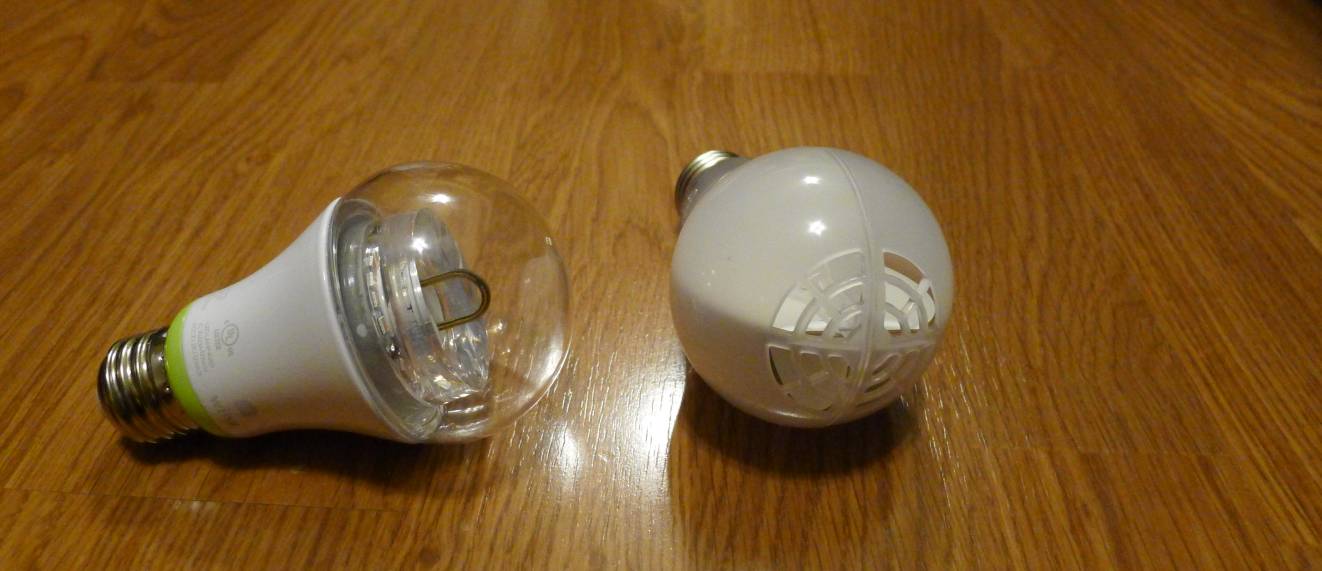
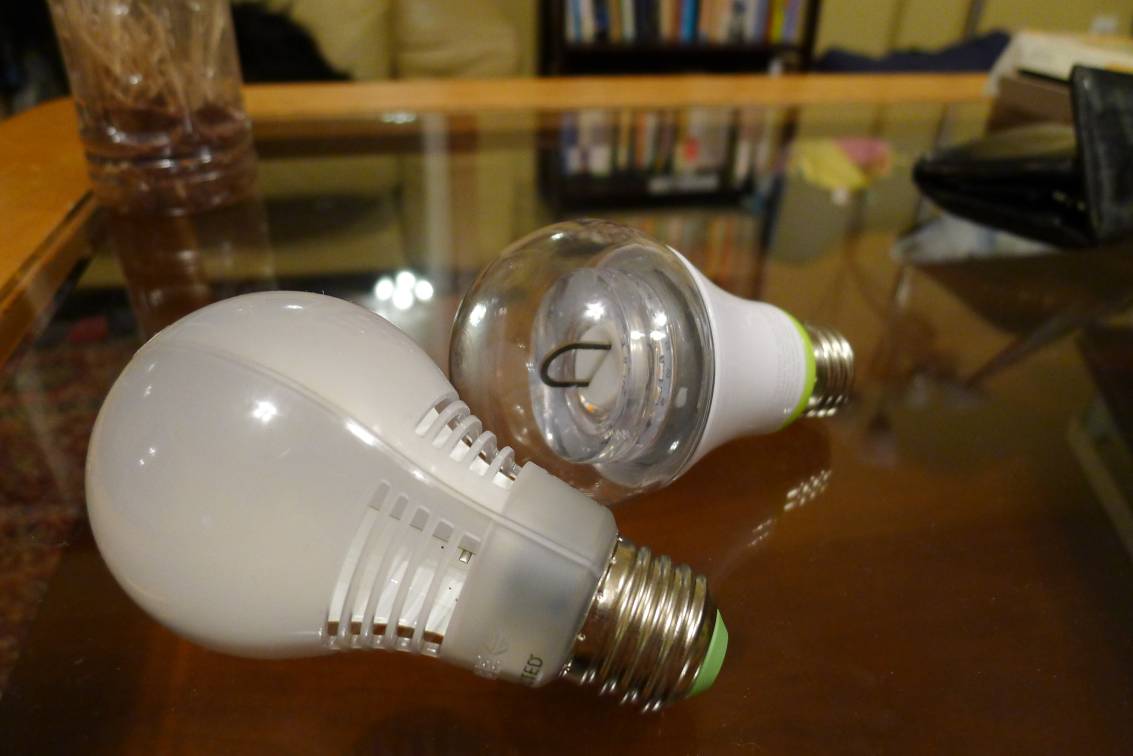
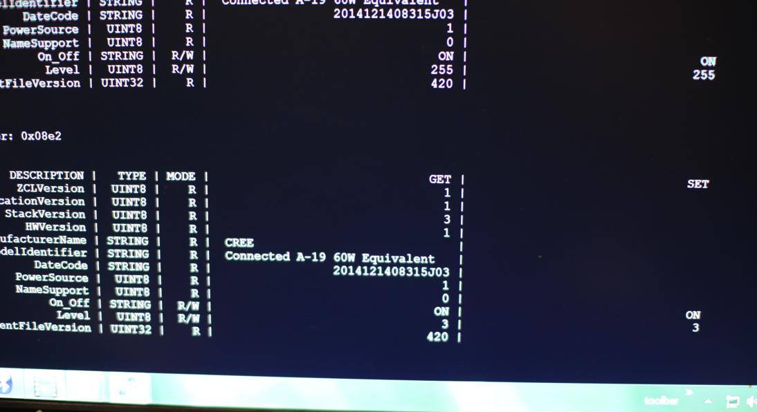
I’m comparing the GE Link bulb (clear globe) with the Cree Connect (frosted globe). They’re both ZigBee bulbs, rated at about the same brightness, and are both compatible with some of the most popular home automation hubs (Wink, Smart Things, Staples Connect). I’m using both on a rooted Wink Hub. The parameters I’m interested in:
1) Electrical power usage and longevity
2) CRI and color temperature
3) Highest high (how bright?)
4) Lowest low (how dim?)
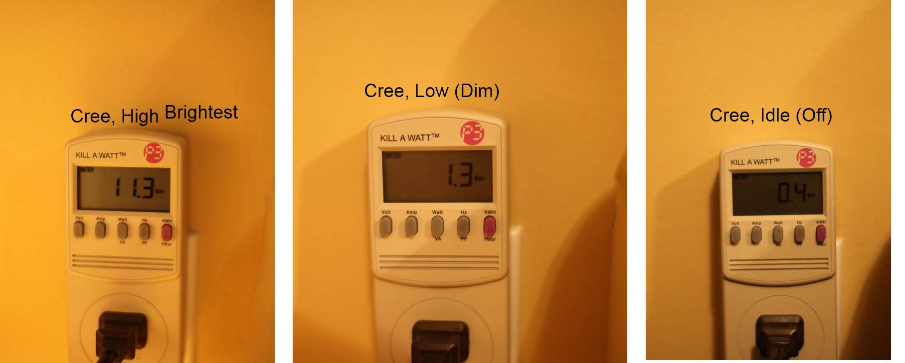
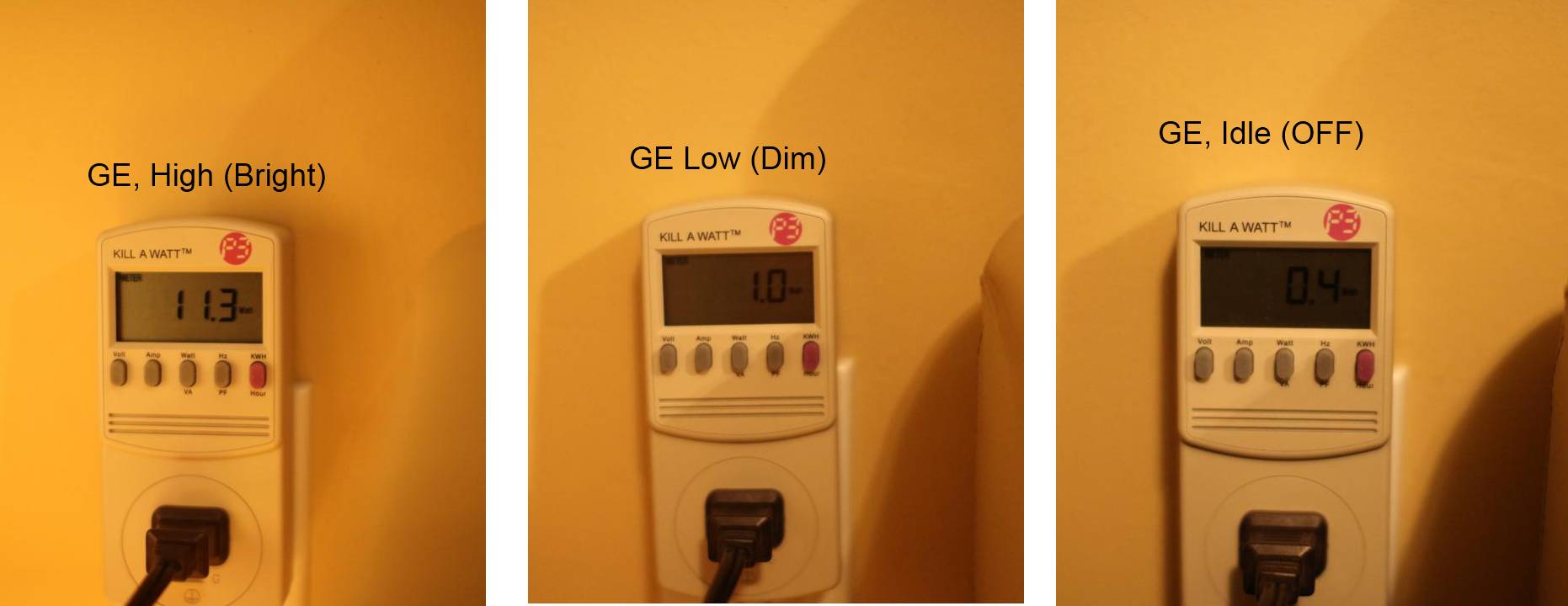
Here’s my readings for energy consumption measured using a Kill-A-Watt. I’m surprised that the bulbs draw 0.4 Watts when they’re in the off state (powered on, but no light output). Most of that is wasted power used to convert AC to the tiny amount of DC current needed for the zigbee microcontroller.
[Watts]
High (Brightest)
Low (Dim)
Idle (Off)
Cree
11.3
1.3
0.4
GE Link
11.3
1.0
0.4
Cree Kill-a-watt
GE Link Kill-a-watt
Let’s assume we’re running a bulb for 5 hours a day at $0.08 per kWH electricity cost. A 60W incandescent would cost $8.70 per year, while these LED’s would cost $1.7 per year. The LED bulbs also have a much longer life expectancy, 25000 hours compared to 2000 hours for incandescent. Even if we halve the listed life expectancy for the LED’s to 12000 hours, that’s over six years bulb life. Over that six years, you’ll spend $42 less in electricity when using LEDs.
When CFL bulbs first came out, they had horrible life expectancy. Mostly I think because of the power electronics (probably capacitors) getting hot and failing over time. But they got much better, and I’ve had CFL bulbs in my living room (highest usage case) that’s lasted six years. It’s not too much of a stretch to believe that the component longevity would extend to these LED bulbs.
CRI & Color Temperature
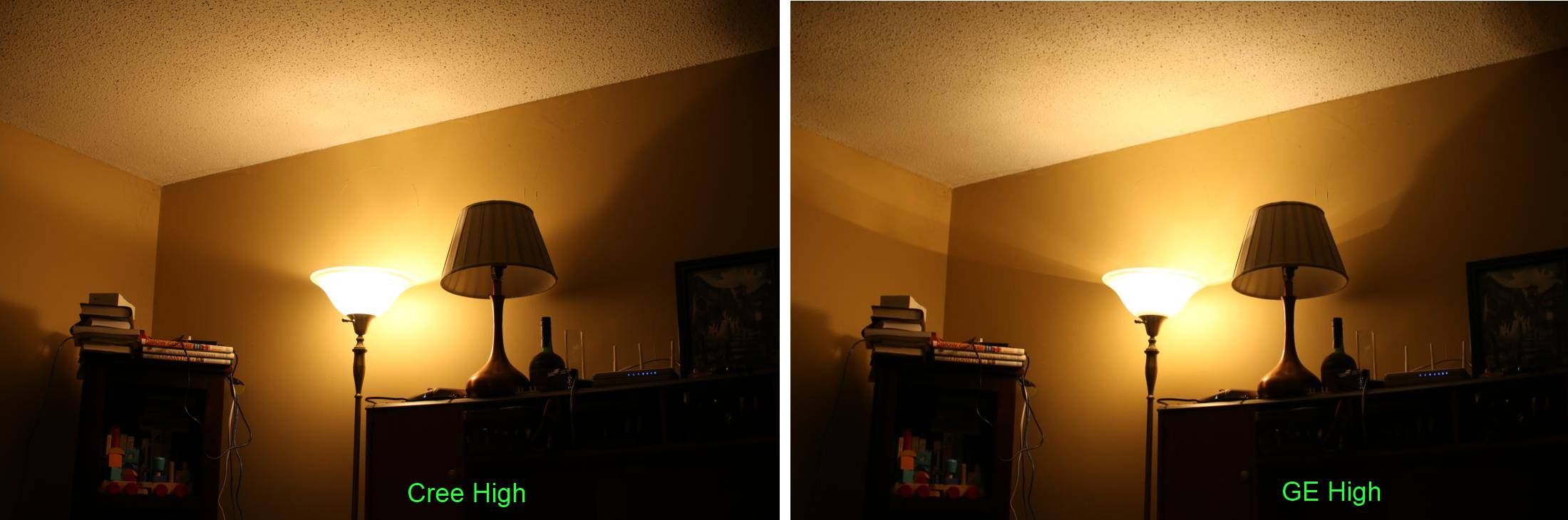
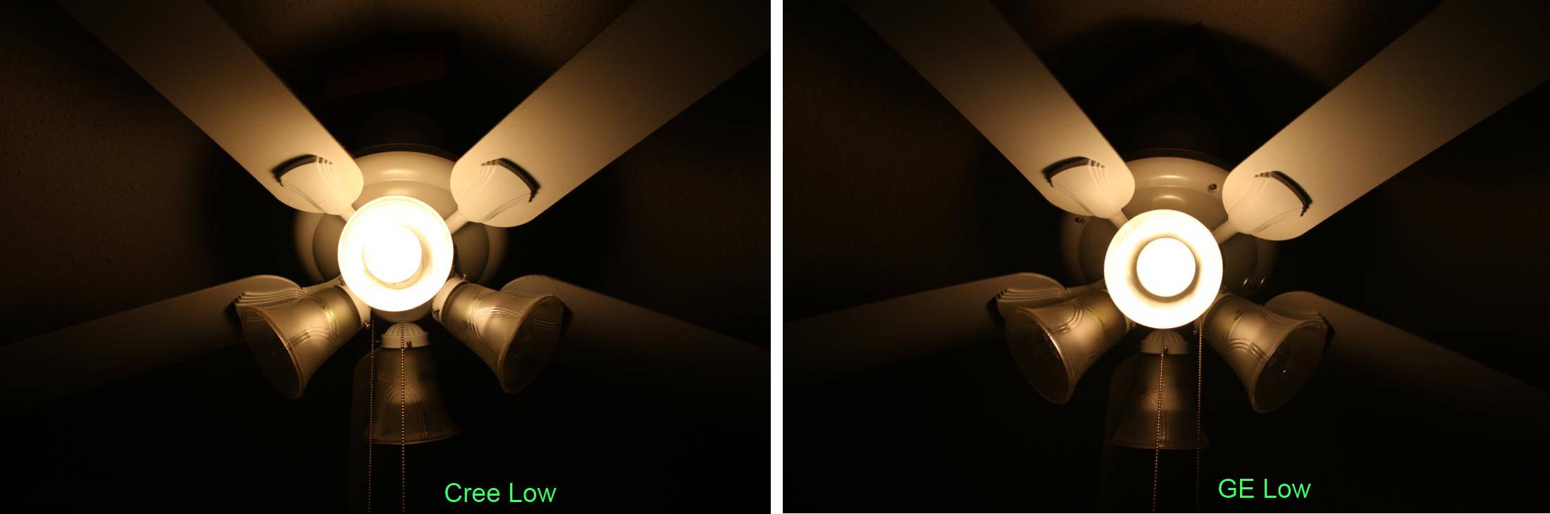
The color temperature looks the same to me, and they’re both rated at 2700k. You can decide for yourself in the photos later. They’re all taken at 4200k white balance on a Canon DSLR (just happen to be at that setting for all the pictures). I should’ve set the color balance on the camera to 2700. Once I started, I wanted to keep all the settings the same, so I just left it as is. As a result, the pictures look really red, but that’s my fault. They’re both nice looking bulbs, and the 2700k rating is about right. I don’t have anything fancy to measure color rendering. They look sameish for CRI.
Highest high
You can decide for yourself. This is with the bulbs turned on manually, so they should be at the highest setting.
Comparison, Brightest
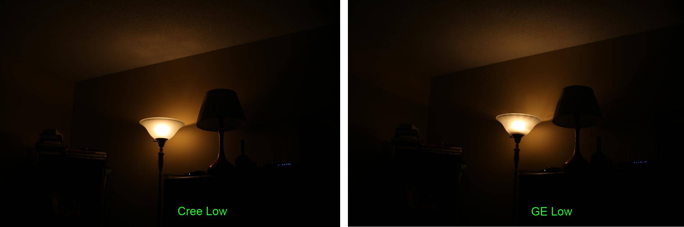
Lowest low
I took all these photos at these settings.
F/4.5
1/30 sec
ISO-400
30mm lens
Color temp: 4200k
To my eyes, both bulbs have about the same low level. The frosted lens on the Cree spreads the light a little differently than the GE, but they look the same if you’re sitting in the room looking around. I wish the bulbs could dim even lower. They’re much too bright as a night light. The low setting is bright enough to let you spot things on the floor before tripping over them.
Comparison, Dimmed,
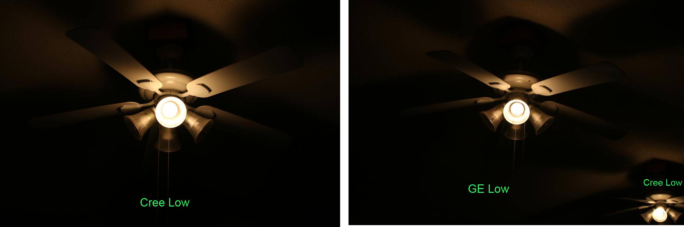
Comparison, Dimmed, overhead lights
Comparison, Dimmed, Up close overhead lights
Testing Details
One note about the low settings. I’m using aprontest on the GE Links to set the low to level=1. On the Cree, I was using the Wink app, which seem to set the low to level=3. Hoping that’s negligible since the value ranges from 1-255.
The best smart bulb on the market (price & performance) is probably the GE Link bulb. For $15, you get a dimmable 800 lumen, 12W LED light bulb that’s controlled via Zigbee. Problem is, how do you control it? How do you automate it?
Mi Casa Verde’s Vera hub? No. No Zigbee radio (as of December 2014 anyways).
SmartThings hub? It’ll work, but you’re forced to use “the cloud”, so if you lose internet (or if ST cloud goes down) you can’t control your lights. But the combination of the ST hub and their Arduino shield gives some alternative methods of lighting control without having to pull out a smart phone.
Wink hub? Same problem as the SmartThings hub (cloud required). That is, until I ran into this and this. So now you can root the hub, and have a means of controlling connected bulbs locally, without haivng to go through Wink’s servers. Since I already have so much stuff integrated with OpenHAB, I wanted to do local control via OpenHAB. And I really don’t like having to depend on the internet to control lights.
Follow the previous two links to root the hub. Next, do the OpenHAB integration using the configuration below.
This is how OpenHAB is used to control Wink Hub
.
OpenHAB screen for controlling GE Link bulbs.
.
You can get fancy with the scenes and control both the bulbs that are on and the individual brightness.
Once the lights are integrated with OpenHAB, they can be used in conjunction with Arduino wireless motion sensors or door sensors to do automation. Or maybe use the lights to indicate that the laundry is complete. The Hub can be completely blocked off from the internet (and Wink servers) with your router’s access restrictions.
If you’re looking for a quick way to control the lights without having to pull out a smart phone or open up a browser, an Arduino or Pi with a IR sensor can be used to receive lighting control from a TV remote. The same shell commands can be activated via MQTT. There’s not very many options in the market for hand-held or wall mounted automation remotes.
Voice Control, Star Trek Style, without any button press.
Voice control is also possible with OpenHAB. Normally, this requires pressing a button prior to giving the voice command, but it’s also possible to do voice control without any prior button presses. An Android phone/tablet with Tasker and the Autovoice plugin can be used to run HTTP post commands directly to the OpenHAB items. Autovoice allows full time voice recognition, so you don’t have to press any buttons to initiate the command. And newer version of Android have the option of downloading the language to the device, so you can keep things local, no internet required. This would be a nice setup for a wall-mounted interface.
1. Create two tasks, lights-on and lights-off. Each task sends a HTTP GET command like this:
Attributes: itm_lights_livingroom=OFF
or itm_scene_livingroom=2
2. Create two profiles. Event > Plugin > AutoVoice > Recognized. Edit the configuration with filter word (“on” or “off”), and go down to Trigger word. I used the trigger word “computer” so I feel like Captain Picard. The trigger word is important because I’m running Autovoice recognition continuously. It’s the equivalent of “Simon saids”. This prevents you from accidentally turn off lights while in conversation.
As commentary, I’m pretty uncomfortable with Wink amassing a database of wifi passwords and locations where they can be used. When you setup the hub, you need to enter your wifi password. And the Wink app gets your phone’s GPS signal (it’s one of the permissions) to do geofencing. OpenHAB can do most of these types of automation tasks, but gives you more control over sensitive data.
The downside to this method is that it’s unidirectional. I can control the lights, but I can’t get the status of the bulbs. Or of other z-wave or zigbee devices connected via the hub. If anyone knows of a way to catch call backs from devices, or install a daemon on the hub itself to perhaps parse aprontest commands and send results via MQTT to the Raspberry Pi, that would be cool.
I hope some company will use open source firmware for their home automation hub, and spawn the first WRT54G of home automation hubs.
Configuration:
Item Definition
Switch itm_lights_livingroom "Living Room Lights"
Number itm_scene_livingroom "Scene"
Number itm_lights_lvl_livingroom "Level [%.1f]"
Switch itm_livingroom_night_light_enb "Auto Night Night"
Switch itm_livingroom_motion_enb "Motion Control"
Solution: Thanks to Peter Hardy and Jan-Piet Mens from the OpenHAB discussion group for pointing out the solution. I moved the client.connect() call to the setup routine instead of calling it every time I need to send an MQTT message. That fixed the problem. I’ll keep this post around for reference.
—————- original post ——————————-
After getting really excited about my wireless Arduino sensor setup, I’ve found some reliability issues. To recap, I’m using an ethernet connected Arduino to relay some wireless sensor data to a MQTT server sitting on the same LAN. It seemed to work pretty reliably, but recently I’ve discovered that sometimes the ethernet Arduino gets into a funk and can’t publish MQTT messages. The problem is that client.connect() is returning false, and continuously returning false for multiple minutes. It’s been hard to find a pattern why it’s doing that. I think client.connect() is part of the ethernet.h library, but not positive.
When there is new data, the sketch loops until clinet.connect() returns true, before going ahead with the MQTT pub. Sometimes it takes many hundred cycles for it to finally return true and I see the MQTT data using Mosquitto. This could be 10 seconds. Other times the data sits in the while loop until finally new data is sent and this data never got sent.
I’ve also verified that the problem isn’t with wireless transmission not being seen by the RFM Arduino gateway. The 915MHz signal really does make it to the RFM Arduino, and is successfully I2C-ed to the ethernet Arduino. The problem seems to be narrowly focused on the client.connect() returning false for minutes at a time.
Things I’ve tried: different router, different ethernet shield (but still Wiznet 5100). Usually the first transmission after a reboot of the Arduino ethernet gateway works.
Here’s the code – please excuse the formatting. Use this link to see better formatting:
#include <SPI.h>#include <Ethernet.h>#include <Wire.h>#include <PubSubClient.h>//I2C receive device addressconstbyteMY_ADDRESS=42;//I2C comms w/ other Arduino//Ethernetbytemac[]={0xxx,0xxx,0xxx,0xxx,0xxx,0xxx};byteserver[]={xxx,xxx,xxx,xxx};EthernetClientethClient;PubSubClientclient(server,1883,callback,ethClient);unsignedlongkeepalivetime=0;voidcallback(char*topic,byte*payload,unsignedintlength){// handle message arrived}voidsetup(){Wire.begin(MY_ADDRESS);Serial.begin(9600);Serial.println("starting");//wait for IP addresswhile(Ethernet.begin(mac)!=1){Serial.println("Error getting IP address via DHCP, trying again...");delay(10000);}//Ethernet.begin(mac, ip);Serial.println("ethernet OK");keepalivetime=millis();Wire.onReceive(receiveEvent);}// end of setupvolatilestruct{intnodeID;//node ID (1xx, 2xx, 3xx); 1xx = basement, 2xx = main floor, 3xx = outsideintsensorID;//sensor ID (2, 3, 4, 5)unsignedlongvar1_usl;//uptime in msfloatvar2_float;//sensor data?floatvar3_float;//battery condition?intvar4_int;}SensorNode;//***** I'm using this flag to indicate that the MQTT msg has not been sent!//this is what is telling me that I haven't succeeded in sending MQTT message.intsendMQTT=0;//**** just a flag to indicate that there's new data to print out on serial monitor.//not very important.volatilebooleanhaveData=false;voidloop(){//print out data on serial monitor.if(haveData){Serial.print("Received Device ID = ");Serial.println(SensorNode.sensorID);Serial.print(" Time = ");Serial.println(SensorNode.var1_usl);Serial.print(" var2_float ");Serial.println(SensorNode.var2_float);sendMQTT=1;//flag that new data avaialble for MQTT.haveData=false;}// end if haveDataif(sendMQTT==1){if(client.connect("arduinoClient"))//*********** BAD, RETURNS ZERO too OFTEN*************{Serial.println("starting MQTT send");//send var2_floatintvarnum=2;charbuff_topic[6];charbuff_message[7];sprintf(buff_topic,"%02d%01d%01d",SensorNode.nodeID,SensorNode.sensorID,varnum);Serial.println(buff_topic);dtostrf(SensorNode.var2_float,4,1,buff_message);client.publish(buff_topic,buff_message);delay(200);//send var3_floatvarnum=3;sprintf(buff_topic,"%02d%01d%01d",SensorNode.nodeID,SensorNode.sensorID,varnum);Serial.println(buff_topic);dtostrf(SensorNode.var3_float,4,1,buff_message);client.publish(buff_topic,buff_message);//set flag to indicate MQTT messages successfully sentsendMQTT=0;Serial.println("finished MQTT send");}//end if client.connectelse{delay(300);//delay a bit before trying to connect again. Not sure if this helps.}}//end if sendMQTT//client.loop();if((millis()-keepalivetime)>10000){client.loop();keepalivetime=millis();}}// end of loop
Some cheap sensors for your wireless Arduino node. Look for them on e*bay for the cheap price.
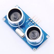
$2, Ultrasonic distance sensor. Good for measuring distance of things, with resolutions down to an inch, and a range of between 3 inch to 6 feet (although I’m unsure about the upper range). May suffer from odd readings because of echo. I’m using this for the garage door monitoring Arduino.
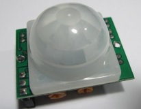
$2, PIR (Infrared) Motion Sensor
I use these as touchless buttons to turn on lights. Also useful as part of a DIY security alarm. These have two pots to adjust sensitivity and duration of the output pin. Watch for variations – some can work at 3.3V, some have to have 5V or more. You may be able to cut the voltage regulator and power it directly from a 3.3V system. Remember the pull-up resistor.
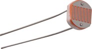
$1, Photoresistor
I use it in the garage to see if the light got left on.
Post 2 of 2 on the topic of Arduino and openHAB for home automation and wireless sensors. Click here to see the first post for the general background information, and also for the actual Arduino sketches that implements this setup. This second post gives more detail regarding MQTT binding between my wireless Arduino sensor and OpenHAB. Read up on how to install Mosquitto here, and the basics of the MQTT protocol here.
Goal: We want the Arduino Gateways (both the RFM Gateway and the Ethernet Gateway) to just work. We don’t want to have to constantly change the sketches on the gateway Arduinos just because we add a new sensor node or add a new device on an existing sensor node. We also don’t want to double manage things. I hope to explain how this double management problem occurs and how to minimize it.
I’ll reuse the communication diagram from the previous post, and reiterate that the “Arduino Gateway” is actually composed of two Arduinos (RFM gateway and Ethernet gateway).
Arduino-OpenHAB Home Automation Architecture
MQTT Message = <topic name> & <data>
topic name = “Topic_Garage_Temperature”
data = 75.2
A MQTT message is composed of two parts: the topic name, and the data itself. With MQTT, there does not seem to be any data types like int and float. On the Ethernet Arduino, you take the floats and ints you get from the sensors, convert them to strings, and send the string off to the MQTT library to be magically sent via ethernet to Mosquitto. Here is a very simplified setup. Click to enlarge.
An overly simplified (but totally workable) way to take wireless data (a float), and put it out on ethernet MQTT to OpenHAB
But this method might be too simple. Using this setup, every time you add a field node, you’ll have to reprogram the two gateway Arduinos in order to account for the new topic name. It’s a pain to have the gateway Arduino sketches identify and convert each field node’s transmission into a unique topic name. You’re managing topic names in both gateway Arduinos and also in OpenHAB. Too many things to go wrong.
Using the RFM69 library, each Arduino is assigned unique Node ID. The Node ID doesn’t have to be an integer, but let’s stick with integers for now.
#define NODEID 40 //unique for each node on same network
You’re responsible for making sure your Node ID’s are unique, so keep a spread sheet of which Arduinos are using which Node ID’s. I’m taking advantage of this unique node ID in order to form parts of the topic name. Hopefully this picture explains a thousand words.
To avoid having to make changes to the gateway Arduino sketches every time a sensor node needs to be added, we’ll automate the formation of unique topic names by taking advantage of the uniqueness of NodeID in the RFM network. I hope this picture makes sense.
Packing Data
Since each field node knows its own node ID (because you assigned it), we’ll embed the unique Node ID into the data structure we defined for wireless transmission. The field Arduino also knows how many sensor devices are connected to it, so we might as well also embed an integer to capture this arbitrarily assigned Device ID. And because we have the freedom to define the wireless transmission structure, we can capture more than one piece of data per transmission, and determine what each data type means on a field node to field node basis. So there’s Var1 (unsigned long int) that can be the millisecond counter, Var2 (float) that can hold the temperature data or whatever, and Var3 (also a float) that can be used eventually for battery power of the field node.
Each time the Arduino Ethernet Gateway receives new data, it actually sends several MQTT messages, one for each of the variables we’re interested in. You’ll notice that not all the data from the wireless transmission struct is actually being sent to MQTT. Only Var2 and Var3 (both floats) are sent to MQTT. Partly because I got lazy. I initially thought I’d care about the millisecond count, but it turned out not to be the case.
The RSSI variable is the wireless transmission strength. See this image. Only the Arduino RFM Gateway knows this information, which is why it injects a new data type, int, to capture the RSSI.
Here’s an example of how I keep track of all the ID’s and topic names.
Spreadsheet for assigning Node ID’s, Device ID’s, and Variable ID’s. Topic names are needed for setting up each item in OpenHAB
The info here is a bit dated – I’ve been updating my buildshere.
Home automation and sensing using Arduino, OpenHAB, and MQTT. With emphasis on low cost (less than $20) wireless sensor nodes. Here’s an example using Arduino to monitor the position of a garage door, and wirelessly report the position to OpenHAB, to be displayed the web interface.
OpenHAB Android app user interface
Arduino Field Device Node
Eventually, I’d like to get to this point.
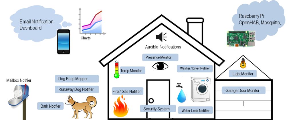
All the sensors for home automation system.
Physical Computing – a doll house replica of the house that mimics real-world activities. Doors/windows open or close when house doors and windows open or close. LED lights in rooms light up when light sensors in those rooms register light.
I want to share a setup for home automation and remote sensing using Arduino and Raspberry Pi. This post will get updated gradually as I build up the system, learn more, make changes to my sketches, or make corrections. So please don’t treat this as a static page. So far, I’ve implemented a single Arduino sensor node in the garage that reports door open/close status, temperature/humidity and light level to OpenHAB, and I have remote access to the OpenHAB interface. There are lots of commercial solutions out there for home automation. Insteon, SmartThings, Revolv, Wemo to name just a few. They differ in the variety of end devices offered as well as the amount of control they provide. I haven’t used any of these systems, partly because they seem to want to trap you into their ecosystem, and partly because the price seems too high for the capability. Building your own home automation system is a lot of fun and you maintain total control over how it works. This is a description of a design based on Arduino and the OpenHAB platform. To establish my requirements for a home automation system, I’ll list the components first:
1) Gateway
2) Field device (node and sensor / actuator)
3) User Interface
Gateway
The gateway is where all the field device data gets sent. It is also the backend to the user interface. The gateway provides the basic functionality of the home automation system. My requirements for the gateway:
Interface with multiple device protocols (more details later)
Provide rules/scenes for automation (if this, then that). The rule generation scheme needs to be flexible. The IF parameter can be sensor data value, sensor data event, time of day, or some input coming from the User Interface. The THEN parameter, the action, should be able to handle actuators in the system, or send emails/notifications, log data for permanent storage, or run a script.
Provide data historization, so you can bring up a chart of sensor data, output status, etc…
Run on a low power computer. The gateway is on 24-7, so energy use is a consideration.
Field Node
The field device is the node to which sensors or actuators are directly attached. It needs to be:
Cheap, so that you can scale up and have many sensors.
Powered by both wall power and batteries, so installation is flexible. For battery power, it should accept cheap batteries and be energy efficient.
The GPIO interface should be capable of accepting many sensors and protocols:
$1.50 PIR presence sensors, digital input
$0.10 photo resistor light sensor, analog input
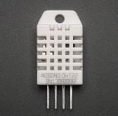
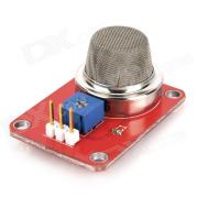
$2.50 temperature/humidity sensor, serial communications
Use wireless transceivers with good range
And of course the field node should communicate wirelessly. Interface The interface for the automation system is ultimately driven by the gateway, so the interface capabilities are tied to the gateway capabilities.
Be able to view sensor status from the interface
Actuate outputs connected to your field devices from the interface
View historical data as a chart
Be able to use the interface on a mobile phone app, or web browser, or perhaps a tablet that can be a permanent home status and control console.
Security – when accessing the gateway remotely, use authentication and encryption.
Field Node Details
I picked Arduino for the field device node. It’s cheap – an Arduino clone is only $10 from ebay. It’s also flexible – there are many detailed discussions online regarding how to build your own Arduino to optimize it for battery power. The ATMEGA328 microcontroller on the Arduino has digital inputs and outputs, analog inputs and outputs, and is capable of talking I2C, SPI, and 1-wire. This covers most sensors out there, as well as display devices like OLED displays, GPS modules, stepper and servo motors amplifiers, etc. There’s also a great community of Arduino users out there to help with programming and wiring. I was able to build my setup thanks to their help.
Arduino Field Device Node
Arduino Field Device Node
Wireless Transceiver
Whatever sensors you connect to an Arduino, you have to send the data back to the gateway somehow. A key component to the entire Arduino-sensor system is the wireless transceiver selection. I ruled out the wifi module – too expensive and power hungry. Z-wave and Xbee are possibilities, but even the cheap ones are expensive, and the cheap ones have poor range. Bluetooth doesn’t have enough range or wall penetration. I’ve personally tested these two different modules: nRF24L01+ and RFM69HW. The nRF24L01+ is probably one of the best known wireless transceiver modules in the Arduino community. It’s cheap. The low power version is $2, and the high power version is $7 (that’s the “+” on the part number). There are multiple libraries available, and the device seems in general to be well supported and widely available. The module and libraries provide basic encryption, so your neighbors can’t monitor your wireless transmissions or actuate your devices. It runs on the 2.4GHz band – the same frequency band as your home wifi. I decided against using it because of the limited range. Here’s a link to a nicely presented range test of the nRF24L01 module. Although he used the low power modules, his results were pretty close to my experience with the high power modules. For me, two high power modules could just barely make it across my house. Start factoring in basements and it gets hairy. I’m also not sure how wifi traffic interferes with the nRF24L01 traffic. Note that I didn’t make any efforts to optimize range by changing the data rates or modifying the antenna. It seems other people were able to get much better range than what I got out of these. I ultimately selected the RFM69HW for my wireless transceiver. It’s a relative newcomer to the Arduino community, and not as well known as the nRF24L01. The Arduino library for the RFM69HW comes from Felix of Low Power Labs. He pretty much single highhandedly provides all the support for this library on his forum. Like the nRF, the RFM69 comes in a standard version (RFM69) and a high power version (RFM69HW), both cost around $4. Here is my personal range test of the RFM69HW modules using a simple 5cm wire antenna. The sender is an Arduino with a GPS module, sending the GPS coordinates using a RFM69HW. The receiver is an Arduino with another RFM69HW, receiving the data as a struct and relaying the data via serial monitor to my computer. The RFM69HW easily makes it through several walls of the house. Communication was pretty reliable up to 7 houses away! That’s way better than my nRF24L01+ results. It’s not quite an apples-apples comparison – the default data rate on the RFM69HW library was lower than the nRF24L01. But the wireless characteristic lead me to deciding on the RFM69HW.
RFM69HW Range Test
One down side of the RFM69HW is that it’s not 5V tolerant. So you either have to power your Arduino with 3.3V, or level shift/voltage divide the pins going to the RFM69HW from the Arduino. It’s not too bad a complication. The RFM69HW is manufactured by HopeRF in China, and it seems you can only get it from their single US distributor, either from ebay or direct from their website. I’ve never had trouble obtaining it, but it seems to be a single sourced component, and perhaps not as widely available as the nRF24L01 if you live in other parts of the world. And HopeRF will stop manufacturing it someday, hopefully not soon. However, it is possible to combine different wireless transceiver modules in the end setup, so it won’t ruin the infrastructure if you change wireless transceivers.
To sum it up:
Characteristic
HopeRF’s RFM69HW
Nordic semiconductor’s nRF24L01+
Range
Over 700ft reliably, good wall penetration with 915MHz frequency
Poor wall penetration, barely makes it across the house, uses the busy 2.4GHz range
Electrical Characteristics
Not 5V tolerant, level shifting required for input pins
Is 5V tolerant, easier to integrate into Arduino
Power
Both modules use 3.3V for power
Price
$4 + reasonable shipping
$6.00
Availability
Single sourced from HopeRF
Seems to be widely available from more than one source
Support
Not as well known in the community, but decent support from Low Power Labs forum.
Very well supported by Arduino community, several libraries available
Encryption
Both wireless modules offer encryption via shared key
Gateway
I picked OpenHAB for my gateway. OpenHAB is a Java application that runs on a computer (Windows, Mac, or Linux). It provides pretty much everything I wanted from a gateway. Once you get the Arduino sensor data into OpenHAB, you can use it’s built-in webserver to display these screen shots below. The OpenHAB interface works as well on a web browser as it does on the Android/iPhone app. The interface is fairly customizable. You define the order and grouping of devices in the list. OpenHAB provides rules and scripts for those “if this then that” situations. You can send email and Android push (or Apple prowl) notifications to your smart phone based on sensor values, time of day, etc. OpenHAB runs on anything that has a recent Java runtime installed – so you can run it from a Windows PC, Apple, or low power $40 Raspberry Pi. The community is friendly, active, responsive, and forward thinking. Best of all, aside from integrating your Arduino sensors and actuators, you can use it to integrate commercial home automation systems via the many bindings. Your OpenHAB infrastructure can support not just your Arduino wireless sensors, but also Insteon, Wemo, Phillips Hue, Z-Wave devices and many more. Expansive!
My OpenHAB interface showing garage door status, temperature, and humidity from the garage Arduino
For more interface examples, check out their demo and their wiki page. I’ve read about several other gateway platforms. Domoticz seems closest to the capabilities offered by OpenHAB, as well as being open sourced. I’d be interested in hearing about others. It does take some time to set up and learn about OpenHAB. Be prepared for that. The optimal installation is on a single board computer with low power consumption running Linux, but you can experiment on a Windows machine, and maybe use one of the newer low power windows set-top boxes.
Tying it all together
I’ll put together wiring diagrams and sketches for the Arduinos in the resource section at the bottom. The key to tying together Arduino with OpenHAB is the MQTT binding. OpenHAB has multiple bindings (plugins) to allow it to talk different protocols, and one such is this MQTT. It’s an open protocol for passing simple messages over ethernet, and is often used by IoT devices for communication. It just so happens that there is also an Arduino library that implements MQTT.
For this to work, you need a central MQTT broker program to receive the messages and disseminate these message to the message subscribers . Besides running the OpenHAB runtime, the Raspberry Pi also runs this MQTT broker program called Mosquitto. The gateway Arduino receives the wireless sensor data via the RFM69HW. Using the Wiznet 5100 ethernet module and the MQTT library from knolleary, the gateway Arduino posts MQTT messages to Mosquitto. OpenHAB uses the MQTT binding to subscribe to MQTT messages from Mosquitto, which is how OpenHAB receives the sensor data. From there, OpenHAB displays the data on the user interface the way you’ve configured. OpenHAB can also act on the data – it can push notifications to your phone when the values exceed some condition you set.
Arduino-OpenHAB Home Automation Architecture
There are other ways of binding data from Arduino to OpenHAB. Some people use the serial binding. The advantage of the serial method is you don’t have to install a MQTT broker like Mosquitto. But there are some compelling reasons to choose MQTT over serial binding.
Placement flexibility – with MQTT, the OpenHAB host computer doesn’t have to be near the wireless Arduino gateway – they just have to be on the same LAN. You can optimize the placement of the Arduino gateway for wireless reception, and place the OpenHAB host computer in a room where you might use it to play audio alarms on sensor events. With serial, the Arduino gateway and OpenHAB host have to be next to each other.
With MQTT, it’s easy to eavesdrop on what the Arduino gateway is transmitting out to OpenHAB; use “mosquitto_sub”.
The MQTT data can be shared by multiple separate OpenHAB installations. There’s a couple scenarios where that might come in handy.
MQTT is useful for other things. Other types of automation systems use MQTT. I plan on doing a project using OwnTracks for GPS mapping (thanks to Jan-Piet Mens’ great contribution there).
Messy Technicality
The terminology gets kind of messy here. The “gateway” I talk about is really OpenHAB running on the Raspberry Pi. The “Arduino Gateway” on the other hand is an Arduino that translates wireless sensor data into ethernet MQTT packets. Ideally, I would just need one Arduino that has a RFM69 transceiver and a Wiznet ethernet shield. But I couldn’t figure out how to get both the RFM69 and the ethernet shield working on the same Arduino – they both talk over SPI, and I hit a wall on changing the device select pin on either the ethernet library or the RFM69 library. So my workaround for this problem is to use two Arduinos – one equipped with the RFM69HW, the other one equipped with the ethernet shield. The RFM-equipped Arduino simply forwards the wireless data to the ethernet-equipped Arduino via I2C master/slave communication. Maybe someday I can fix this issue, or a reader can point the way to a solution, but for now, that’s how it works. Just know that the “Arduino gateway” is actually composed of two Arduinos, and the “gateway” is a Raspberry Pi running OpenHAB and Mosquitto.
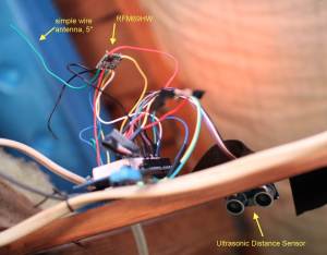
Arduino Gateway – The left Arduino has the wireless transceiver (RFM69HW) w/ a 5″ green antenna wire. The right Arduino has the ethernet shield. Wireless sensor data is sent from the RFM Arduino to the Ethernet Arduino via I2C. The Ethernet Arduino sends MQTT data to Raspberry Pi via ethernet.
The Home Automation Part
So none of this is really “home automation”. It’s just sensing. The automation part is handled by OpenHAB, and you can get a much clearer idea of the possibilities by going over to the tips section of the OpenHAB wiki. As an example, you can have the Raspberry Pi tell you about the garage door by adding a few lines in /configuration/rules/demo.rules:
rule “Say Garage Door”
when Item itm_garage_door changed from CLOSED to OPEN
then say(“Someone messed with the garage door, Batman!”)
end
Oh yeah, did I mention that OpenHAB talks? It’s that cool. Replace the $2 ultrasonic distance sensor with a $2 PIR presence sensor. You can have it announce that someone is at the door, or send a email to you when presence is detected.
Reliability and Future Plans
The simple system I have right now has been running 24/7 for a few weeks. It recovers gracefully from power failures. I had one hiccup when I was messing with it to take pictures for this post, one of the wires for the I2C between the gateway Arduinos came off. It required a power cycle of the Arduinos to get going again. Everything could do with a bit more soldering and a bit less breadboard prototyping.
As of now, my setup only works for one way communication – field nodes sending sensor data to OpenHAB. This is because the I2C master-slave communication between the two gateway Arduinos is unidirectional. I’ll have to investigate if I can use another RFM-Arduino to be the I2C slave that receives commands from the Ethernet-Arduino. Otherwise, it’ll be trivial to add yet another pair of Arduino gateways strictly for MQTT message monitoring – MQTT messages from OpenHAB to the Arduino for actions. But that seems cumbersome. The whole problem might go away if I’m able to use a single Arduino for the gateway, or use serial communication between the gateway Arduinos instead of master/slave I2C.
I’ll also be experimenting with a battery powered Arduino design in the near future. Being battery powered adds a whole set of other design requirements.
Click here for Part 2, giving more details on how the two gateway Arduinos are programmed and how to form topic names.
Future work for this post
1) clean up comments in Arduino sketch, better explain struct usage for sensor data, and the arbitrary numbering scheme for MQTT topic name.
2) post wiring diagrams
3) post sanitized OpenHAB config, item file, sitemap file
4) post Mosquitto configuration
5) post common issues to look out for, and all the other details I’ve not had time to write out.
Arduino Sketches:
Go to my github for all Arduino sketches and openhab configurations regarding this topic.
2) $10 Arduino Buono: a nice Arduino clone that has a 3.3V / 5V switch. Set switch to 3.3V to avoid frying the RFM69HW. Also, this clone has a pretty high max amps for the 3.3V power rail, so no need to use another voltage regulator to power the RFM69HW. You can search ebay for “Arduino Buono” to find it.
5) $21 The Moteino is an Arduino clone that can be purchased with the RFM69HW built in. The creator of the RFM69 library, Felix of Low Power Labs, sells it on his webstore. It comes all soldered up and is pretty energy efficient, good for battery powered sensors. So if you don’t want to do any soldering, you can use this instead of the Arduino. Felix seems like a nice guy, shares a lot of his knowledge freely. The Low Power Lab blog has some neat project ideas.
Links to resources:
Arduino MQTT library, works with Wiznet 5100 ethernet shield